
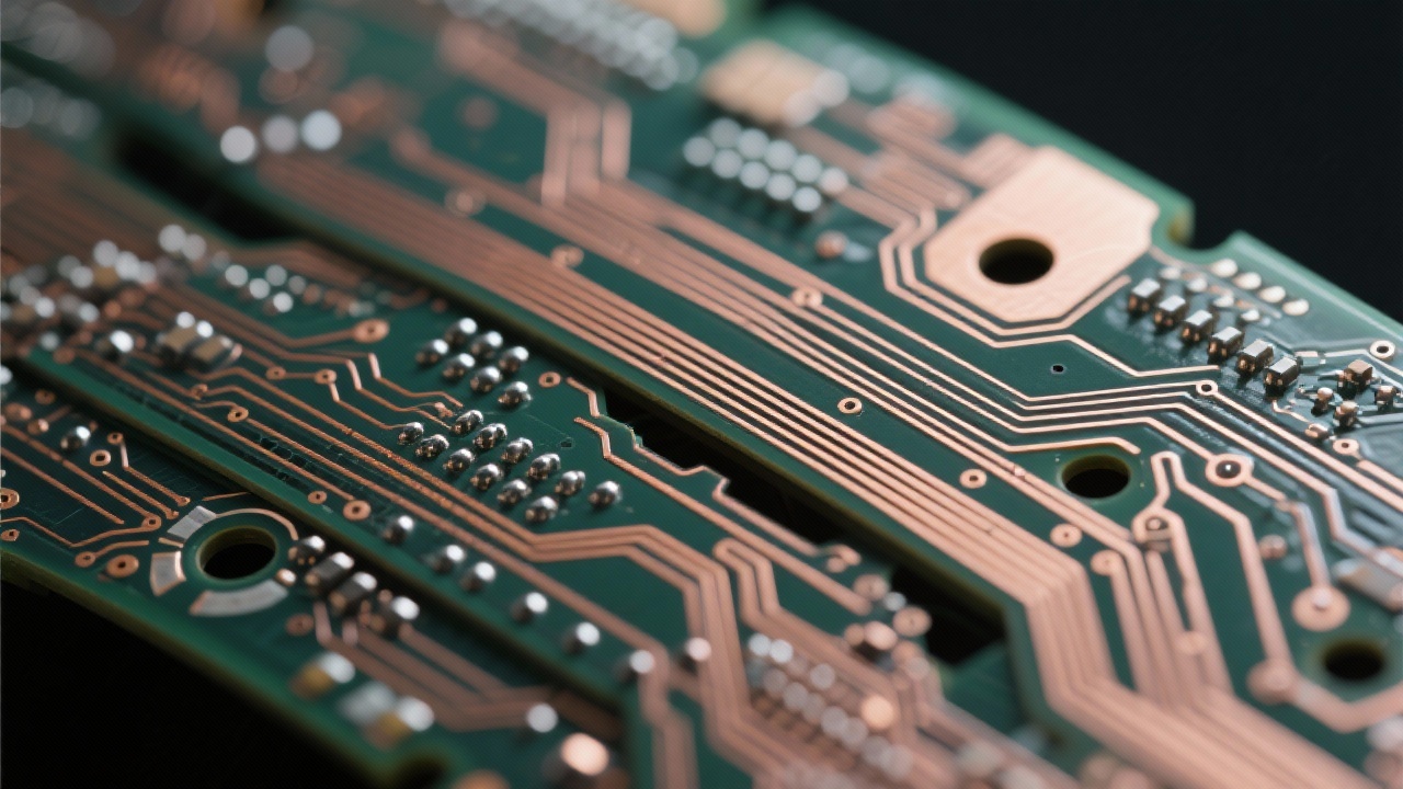
In the realm of high - speed multilayer PCB design, impedance control is a fundamental and crucial technology. In the telecommunications industry, ensuring stable impedance is essential for high - speed signal transmission. For instance, in high - speed signal transmission, the 50 - ohm single - ended and 100 - ohm differential pair impedance standards play a key role. A well - controlled impedance can effectively reduce signal reflection and crosstalk, thus improving the integrity of the signal.
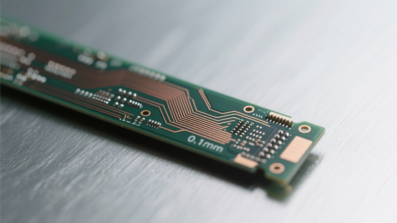
Single - ended 50 - ohm and differential 100 - ohm impedance standards have a significant impact on signal transmission. In high - speed circuits, if the impedance is not matched, it can lead to a series of problems such as signal attenuation, distortion, and increased bit error rate. Research shows that when the impedance mismatch exceeds 10%, the signal quality can be significantly degraded, affecting the performance of the entire communication system.
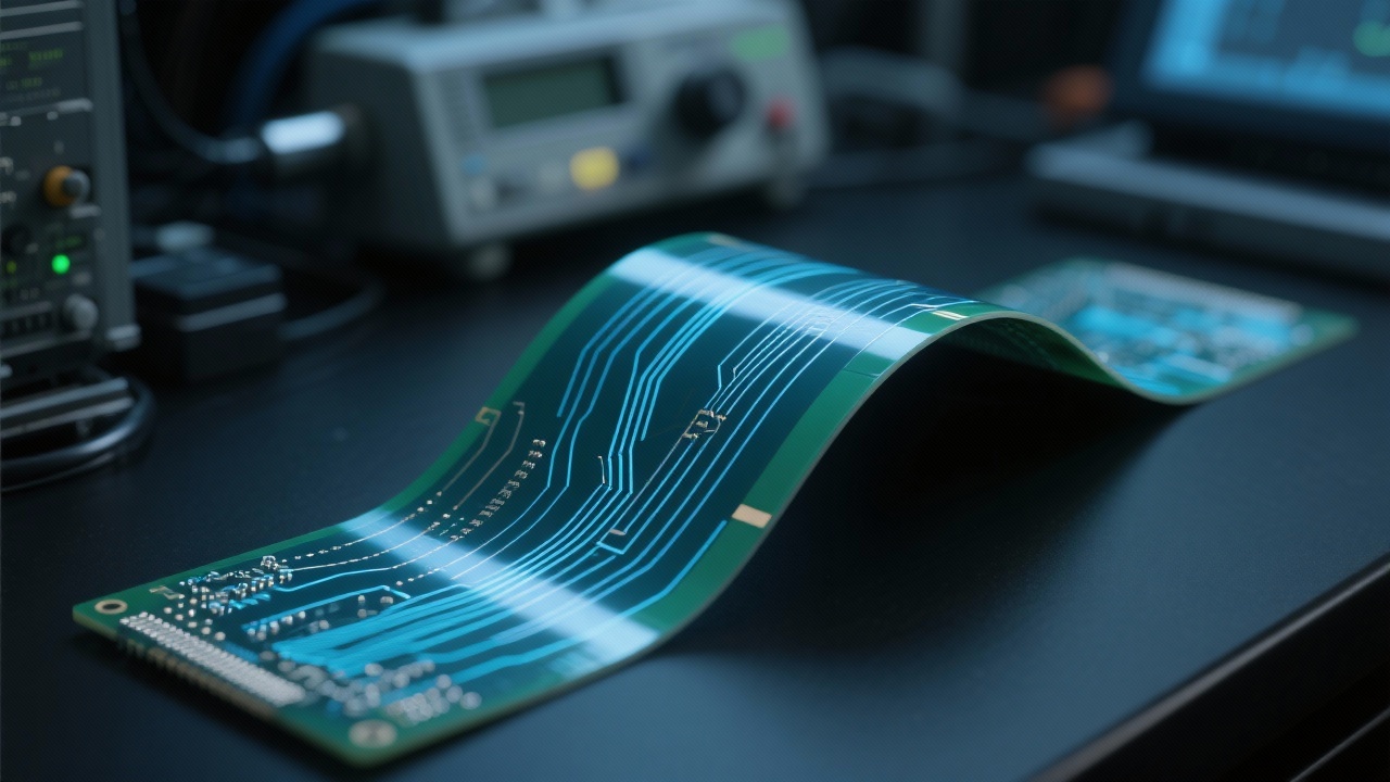
In 5G base stations and high - frequency communication modules, impedance matching is of utmost importance. Take 5G base stations as an example. The high - speed data transmission between multiple antennas and signal processing units requires strict impedance control. By implementing impedance matching design, the signal loss can be reduced by up to 30%, greatly improving the efficiency of data transmission.
In practical applications, impedance matching design involves multiple aspects. Firstly, choosing the right materials is crucial. High - performance dielectric materials such as ISOLA 370HR and MENTRON6 have excellent electrical properties, which can effectively ensure impedance stability. Secondly, the precision lamination process is also essential. Through a reasonable lamination structure, the signal interference between different layers can be reduced, and the signal integrity can be improved.
To ensure the quality of high - speed PCBs, impedance measurement and verification are essential steps. Design simulation tools can help engineers predict the impedance performance of PCBs in the design stage, allowing them to make timely adjustments. After production, AOI (Automated Optical Inspection) technology can be used for strict detection. AOI technology can detect tiny defects on the PCB surface, ensuring the accuracy of impedance and the overall quality of the product.
In conclusion, impedance control is a key factor in ensuring the quality and performance of high - speed multilayer PCBs. Whether it is in 5G base stations or high - frequency communication modules, proper impedance matching and strict quality control can help engineers optimize the design process and improve product reliability. If you are a PCB design or communication equipment R & D engineer and want to learn more about high - frequency high - speed PCB technology and production solutions, click here to get professional guidance and support.
 358
|
358
|
 FPC Hochdichte Leiterplatten
Flexible PCB Design Techniken
Elektromagnetische Verträglichkeit
Hochdichte flexible Leiterplatten
Flexible PCB Fertigung
247
|
FPC-Hochdichte-Bestückung
Flexibles PCB-Design
Leitungsabstand bei FPC
EMV-Optimierung für flexible Leiterplatten
FPC-Fertigungsprozess
459
|
FPC Via Design
FPC Biegebereich Spannungskonzentration
Flexibles Leiterplatten Design
Hochdichtverdrahtung
Signalintegrität FPC
298
|
Hochdichte Verdrahtung von FPCs
Designtechniken für flexible Leiterplatten
Optimierung der elektromagnetischen Verträglichkeit
Schutz gegen Signalkreuzstörungen
Herstellung von FPCs mit hoher Zuverlässigkeit
265
|
FPC high - density wiring
Flexible printed circuit design skills
Microhole processing technology
Electromagnetic compatibility optimization
High - reliability flexible PCB
FPC Hochdichte Leiterplatten
Flexible PCB Design Techniken
Elektromagnetische Verträglichkeit
Hochdichte flexible Leiterplatten
Flexible PCB Fertigung
247
|
FPC-Hochdichte-Bestückung
Flexibles PCB-Design
Leitungsabstand bei FPC
EMV-Optimierung für flexible Leiterplatten
FPC-Fertigungsprozess
459
|
FPC Via Design
FPC Biegebereich Spannungskonzentration
Flexibles Leiterplatten Design
Hochdichtverdrahtung
Signalintegrität FPC
298
|
Hochdichte Verdrahtung von FPCs
Designtechniken für flexible Leiterplatten
Optimierung der elektromagnetischen Verträglichkeit
Schutz gegen Signalkreuzstörungen
Herstellung von FPCs mit hoher Zuverlässigkeit
265
|
FPC high - density wiring
Flexible printed circuit design skills
Microhole processing technology
Electromagnetic compatibility optimization
High - reliability flexible PCB


-4.png?x-oss-process=image/resize,m_fill,h_800,w_800/format,webp)


-L4-4.png?x-oss-process=image/resize,m_fill,h_800,w_800/format,webp)
-4.png?x-oss-process=image/resize,h_800,m_lfit/format,webp)


