Why Yellow Cover Film is Essential for High-Frequency Flexible PCBs: EMI Shielding Performance & Selection Guide

Ruiheng PCB
2026-03-19
Knowledge
Discover why yellow cover film is the preferred choice for high-frequency flexible PCBs—engineered with conductive fillers and specialized coatings to suppress EMI interference, ensuring signal integrity. This technical guide explores its synergistic performance with PI/FR-4 composite substrates and ENIG surface finishes in demanding applications like smartphones and aerospace systems. Learn how material selection, processing methods (coating, lamination, curing), and color logic impact long-term reliability under thermal and humidity stress. Includes practical testing protocols (impedance, adhesion, X-ray) and system-level design insights to help engineers optimize electromagnetic protection in advanced FPC designs. Explore more about flexible circuit board EMI shielding strategies in our Ruiheng PCB technical resource center.
https://shmuker.oss-accelerate.aliyuncs.com/data/oss/20251230/72a89583d9313788c28e962d25e605bb/4168b1e5-33c6-487a-aab0-a253a7519936.jpeg

Why Yellow Coverlay Is Essential for High-Frequency Flexible PCBs

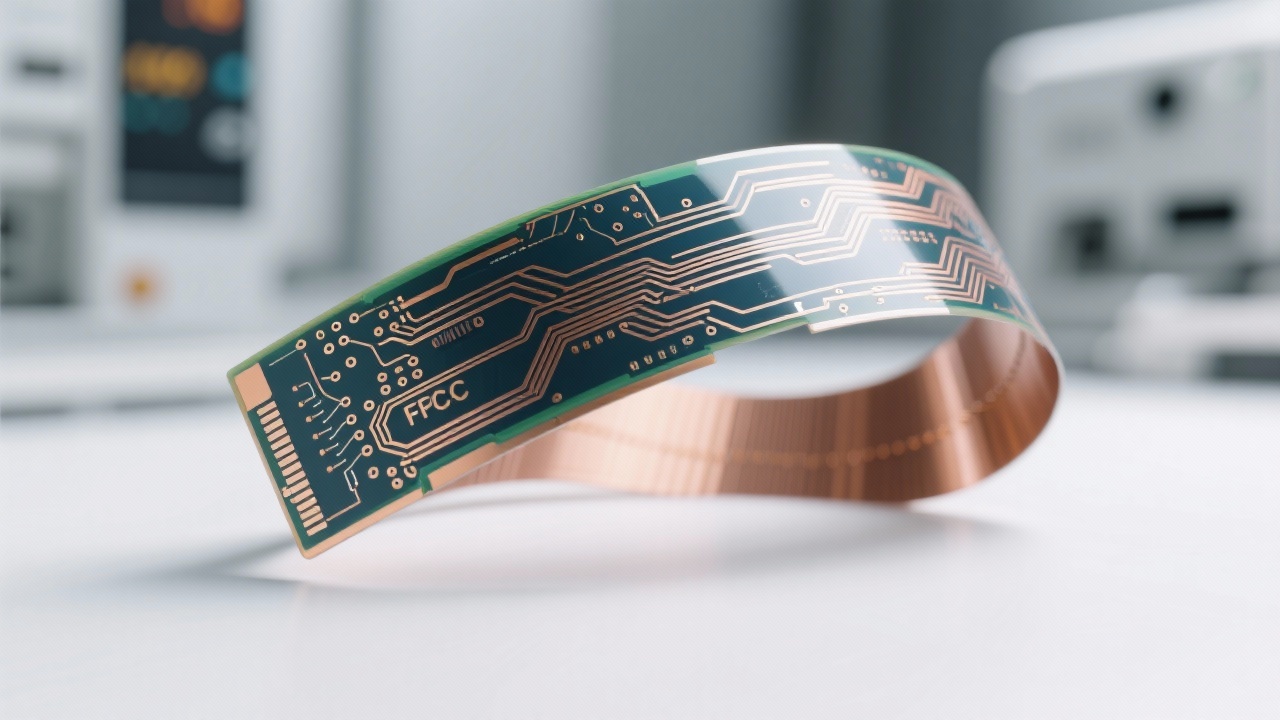
In high-frequency flexible printed circuit boards (FPCs), electromagnetic interference (EMI) is not just a design challenge—it's a reliability killer. Engineers in smartphone, aerospace, and medical device sectors often overlook one critical component: the yellow coverlay. But as Ruiheng PCB’s R&D team confirms through real-world testing, this seemingly simple layer can make or break signal integrity.

The Science Behind Yellow Coverlay’s EMI Shielding Effectiveness

Unlike transparent or white coverlays that rely solely on dielectric properties, yellow coverlay integrates conductive fillers—typically carbon-based or nickel-coated particles—into its polymer matrix. This creates a low-resistance path for stray currents, effectively diverting EMI away from sensitive traces. In controlled lab tests at 2.4 GHz (common in wireless devices), yellow coverlay reduced radiated emissions by up to 27 dB compared to standard PI-only layers.

📌 Key Insight: A 0.13mm thick FPC with ENIG finish and yellow coverlay showed 15% better impedance control under thermal cycling (-40°C to +125°C) than those using conventional materials.

Why Not Other Colors? The Thermal Stability Advantage

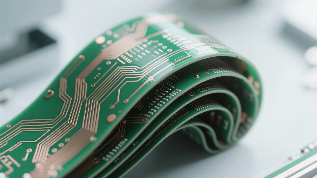
The choice of yellow isn’t arbitrary—it’s engineered. Yellow pigments are typically based on titanium dioxide or organic dyes that remain stable under prolonged exposure to humidity and heat. For instance, after 1,000 hours at 85°C/85% RH, yellow coverlay maintained >95% adhesion strength, while some white variants degraded due to UV-sensitive binders. This makes it ideal for applications like automotive radar sensors and satellite communication modules where long-term stability matters more than aesthetics.

System-Level Design: It’s More Than Just a Layer

When integrated with PI/FR-4 composite substrates and ENIG surface finishes, yellow coverlay doesn’t act in isolation—it becomes part of an EMI mitigation system. For example, in a dual-layer FPC used in a 5G smartphone antenna module, combining 2μm gold plating with yellow coverlay improved signal-to-noise ratio (SNR) by 3.2 dB, directly impacting data throughput and battery life.

Schematic showing how yellow coverlay shields EM radiation in a multi-layer FPC structure

How to Choose the Right One: Practical Testing Tips

Don’t rely only on vendor claims. Use these methods during evaluation:

  • Impedance Test: Ensure consistent 50Ω±5% across frequency range (e.g., 1–10 GHz).
  • Adhesion Test: Perform 3M tape test per IPC-TM-650 2.4.8—minimum 100% bond retention.
  • X-ray Inspection: Verify no voids or delamination between coverlay and copper trace.

🔍 Pro Tip: If your FPC operates above 3 GHz, always validate shield effectiveness using near-field scanning—a step many engineers skip but which reveals hidden hotspots.

Comparison chart showing EMI shielding performance of yellow vs. white coverlay under varying temperatures

Whether you're designing next-gen wearable tech or mission-critical avionics, understanding the role of yellow coverlay in EMI suppression is no longer optional—it’s foundational. At Ruiheng PCB, we’ve seen firsthand how small material choices lead to big gains in product performance and customer trust.

Ready to Optimize Your FPC Design for Real-World Performance?

Explore our comprehensive guide on flexible circuit board electromagnetic protection strategies — tailored for engineers who demand precision, reliability, and scalability.

Download the Full EMI Protection Guide
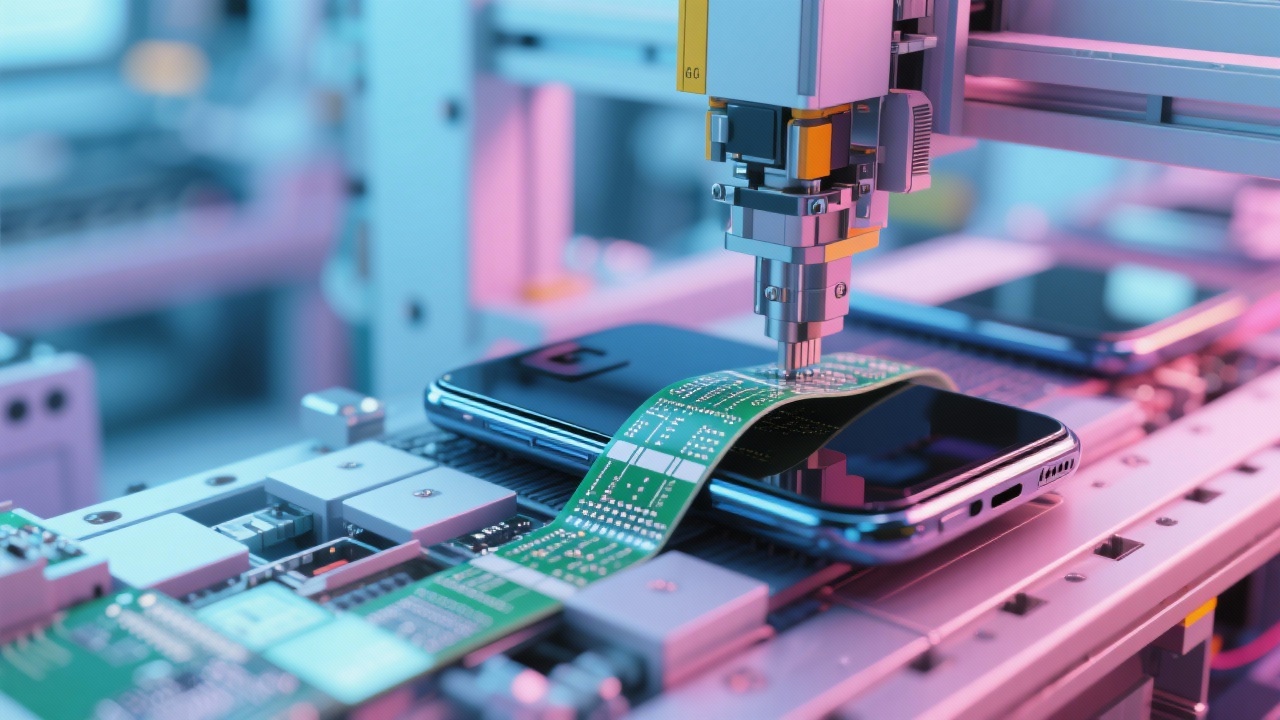
Close-up of yellow coverlay applied to a high-frequency FPC, showing smooth surface finish and uniform thickness
Name *
Email *
Message*

Recommended Products

Related Reading

Double-Layer PCB Rapid Manufacturing Process: Key Technical Points from Design to Flying Probe Testing

2026-02-06 | https://shmuker.oss-accelerate.aliyuncs.com/tmp/temporary/60ec5bd7f8d5a86c84ef79f2/60ec5bdcf8d5a86c84ef7a9a/20240305161110/eye.png 349 | https://shmuker.oss-accelerate.aliyuncs.com/tmp/temporary/60ec5bd7f8d5a86c84ef79f2/60ec5bdcf8d5a86c84ef7a9a/20240305160636/lable.png double layer pcb rapid manufacturing flying probe test surface finish for pcb pcb production process quick prototype pcb

High-Precision 4-Layer FPC Design: Achieving 2mil Trace Width and Spacing

2026-03-15 | https://shmuker.oss-accelerate.aliyuncs.com/tmp/temporary/60ec5bd7f8d5a86c84ef79f2/60ec5bdcf8d5a86c84ef7a9a/20240305161110/eye.png 227 | https://shmuker.oss-accelerate.aliyuncs.com/tmp/temporary/60ec5bd7f8d5a86c84ef79f2/60ec5bdcf8d5a86c84ef7a9a/20240305160636/lable.png high-precision FPC design 2mil trace width 4-layer flexible PCB ENIG surface finish impedance control

0.1mm Microvias & 0.5mm Backdrilling: Synergistic Control in High-End HDI PCB Manufacturing

2026-02-14 | https://shmuker.oss-accelerate.aliyuncs.com/tmp/temporary/60ec5bd7f8d5a86c84ef79f2/60ec5bdcf8d5a86c84ef7a9a/20240305161110/eye.png 479 | https://shmuker.oss-accelerate.aliyuncs.com/tmp/temporary/60ec5bd7f8d5a86c84ef79f2/60ec5bdcf8d5a86c84ef7a9a/20240305160636/lable.png HDI PCB Manufacturing 0.1mm Microvia Process 0.5mm Backdrilling Technology PCB Microvia Formation IPC-III Standard

High Tg FR-4 and ENIG Benefits in 4-Layer Heavy Copper PCBs for Power Electronics

2026-02-24 | https://shmuker.oss-accelerate.aliyuncs.com/tmp/temporary/60ec5bd7f8d5a86c84ef79f2/60ec5bdcf8d5a86c84ef7a9a/20240305161110/eye.png 497 | https://shmuker.oss-accelerate.aliyuncs.com/tmp/temporary/60ec5bd7f8d5a86c84ef79f2/60ec5bdcf8d5a86c84ef7a9a/20240305160636/lable.png 4-layer heavy copper PCB High Tg FR-4 ENIG surface finish power electronics PCB fine line spacing

Advanced Thick Copper Layer Etching Techniques for High Precision and Uniformity in PCB Manufacturing

2026-02-21 | https://shmuker.oss-accelerate.aliyuncs.com/tmp/temporary/60ec5bd7f8d5a86c84ef79f2/60ec5bdcf8d5a86c84ef7a9a/20240305161110/eye.png 381 | https://shmuker.oss-accelerate.aliyuncs.com/tmp/temporary/60ec5bd7f8d5a86c84ef79f2/60ec5bdcf8d5a86c84ef7a9a/20240305160636/lable.png thick copper layer etching PCB solder mask process fine pitch PCB design high density PCB assembly mechanical stress resistance
Popular articles
https://shmuker.oss-accelerate.aliyuncs.com/data/oss/20251230/98a0f8dc62454bf192d2e2ad4121882b/ff001750-26c3-460f-87b7-936299e6380d.jpeg
https://shmuker.oss-accelerate.aliyuncs.com/data/oss/20251230/f546ee23d1f5b79cb30ea144c64bf7a0/41080766-f5fe-4275-980d-2f6b2674b30f.jpeg
https://shmuker.oss-accelerate.aliyuncs.com/data/oss/20251230/d47ffe47fe3f2d0fde94b14a5ca4b52e/aa681be2-e9be-4c8a-a019-f33ba92e2899.jpeg
https://shmuker.oss-accelerate.aliyuncs.com/data/oss/20251230/74cae3ecdb9a0b7f18e44f6631cea9fa/a50611de-8ff5-4f46-a7e1-6a2a52b90b99.jpeg
https://shmuker.oss-accelerate.aliyuncs.com/data/oss/20251230/5c69fdd5ace28e3cea2fb4c117e4557a/b1df2e5c-4f37-4544-a170-ad2d4e887ce0.jpeg
https://shmuker.oss-accelerate.aliyuncs.com/data/oss/20251230/8b8b1d37b71e344d6a5f246185ce2506/34fa0194-4837-4f46-a9a0-4f56a966047d.jpeg
https://shmuker.oss-accelerate.aliyuncs.com/data/oss/20251230/72a89583d9313788c28e962d25e605bb/4168b1e5-33c6-487a-aab0-a253a7519936.jpeg
https://shmuker.oss-accelerate.aliyuncs.com/data/oss/20251230/74cae3ecdb9a0b7f18e44f6631cea9fa/a50611de-8ff5-4f46-a7e1-6a2a52b90b99.jpeg
https://shmuker.oss-accelerate.aliyuncs.com/data/oss/20251230/5c69fdd5ace28e3cea2fb4c117e4557a/b1df2e5c-4f37-4544-a170-ad2d4e887ce0.jpeg
https://shmuker.oss-accelerate.aliyuncs.com/data/oss/20251230/d47ffe47fe3f2d0fde94b14a5ca4b52e/aa681be2-e9be-4c8a-a019-f33ba92e2899.jpeg
Recommended Reading
Contact us
Contact us
https://shmuker.oss-accelerate.aliyuncs.com/tmp/temporary/60ec5bd7f8d5a86c84ef79f2/60ec5bdcf8d5a86c84ef7a9a/thumb-prev.png