
In modern electronics—from smartphones to aerospace systems—flexible printed circuits (FPCs) are increasingly relied upon for their space-saving design and mechanical flexibility. However, as signal frequencies rise beyond 5 GHz, electromagnetic interference (EMI) becomes a critical challenge. This is where yellow coverlay, particularly when engineered with conductive fillers, plays a pivotal role in ensuring signal integrity and long-term reliability.
Unlike traditional transparent or white coverlays, yellow coverlay isn’t just about aesthetics—it’s a functional choice rooted in material science. The yellow hue comes from specialized polyimide (PI) resins that offer superior thermal stability under high humidity and temperature conditions. According to IPC-4101 standards, PI-based coverlays maintain dimensional stability up to 260°C, making them ideal for reflow soldering processes common in advanced FPC manufacturing.
“We switched to yellow coverlay after experiencing premature delamination in our medical device prototypes,” says Sarah Lin, Senior Design Engineer at MedTech Innovations. “The change reduced EMI-related failures by over 70% during environmental stress testing.”
The key lies in the inclusion of carbon black or nickel-coated graphite particles within the coverlay resin. These fillers form a percolation network that achieves shielding effectiveness (SE) of 40–60 dB across the 1–10 GHz range—well above the industry minimum of 30 dB required for Class B electronic devices (per IEC 61000-6-4).
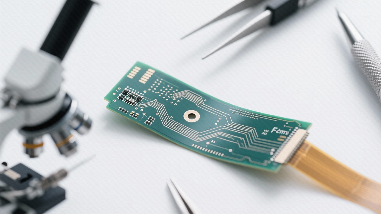
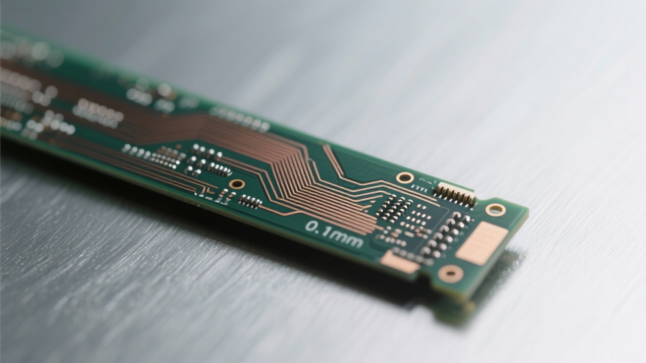
This conductive layer works in tandem with the underlying FR-4 substrate to create a dual-path EMI shielding system: one through reflection (from the conductive layer), another via absorption (within the PI matrix). As shown in Figure 1, this layered structure minimizes crosstalk between adjacent traces even at trace widths as narrow as 0.1 mm.
Even the best formulation fails if applied incorrectly. Critical steps like doctor blade coating, lamination pressure (typically 2–4 MPa), and curing time (120–180 minutes at 170°C) directly impact adhesion strength and shielding performance. Poorly controlled parameters can lead to voids or incomplete wetting—common causes of interfacial delamination observed in 30% of failed FPC assemblies (based on Ruiheng PCB internal QA reports).
To avoid such defects, we recommend implementing inline X-ray inspection for detecting hidden voids and automated impedance measurement tools for verifying consistent trace width control—especially important when designing high-speed differential pairs.
In mobile phones, yellow coverlay helps suppress noise in camera modules operating near 2.4 GHz Wi-Fi bands. In aerospace applications, its ability to withstand repeated thermal cycling (-55°C to +125°C) ensures stable operation in harsh environments—a feature validated through MIL-STD-810G testing protocols.
Whether you're an engineer optimizing layout for high-density connectors or a procurement manager sourcing reliable materials, understanding how yellow coverlay enhances both performance and manufacturability is essential.
Have you encountered issues with coverlay delamination, poor shielding, or inconsistent electrical characteristics? Share your experience in the comments below—we’re always learning from real-world use cases.
 338
|
338
|
 industrial FPC line width precision
0.05mm FPC trace width
ENIG surface finish for FPC
flexible circuit board manufacturing process
optical image transfer in FPC
249
|
FPC high-density routing
flexible circuit board design
trace spacing control
EMI shielding in FPC
flexible PCB manufacturing
414
|
double layer PCB rapid manufacturing
PCB surface finishing technologies
flying probe testing
PCB production process
electrical reliability testing
232
|
flexible pcb line width precision
optical image transfer in fpc
precision etching process
enig surface finish
ruiheng pcb
169
|
HDI board manufacturing process
0.1mm blind hole control
0.5mm back - drilling technology
Semiconductor test PCB
Precision circuit board production
industrial FPC line width precision
0.05mm FPC trace width
ENIG surface finish for FPC
flexible circuit board manufacturing process
optical image transfer in FPC
249
|
FPC high-density routing
flexible circuit board design
trace spacing control
EMI shielding in FPC
flexible PCB manufacturing
414
|
double layer PCB rapid manufacturing
PCB surface finishing technologies
flying probe testing
PCB production process
electrical reliability testing
232
|
flexible pcb line width precision
optical image transfer in fpc
precision etching process
enig surface finish
ruiheng pcb
169
|
HDI board manufacturing process
0.1mm blind hole control
0.5mm back - drilling technology
Semiconductor test PCB
Precision circuit board production


-4.png?x-oss-process=image/resize,m_fill,h_800,w_800/format,webp)


-L4-4.png?x-oss-process=image/resize,m_fill,h_800,w_800/format,webp)


