
In 5G and high-frequency communication systems, impedance stability directly affects signal integrity and device reliability. This article delves into how high-performance dielectric materials, such as ISOLA 370HR and MENTRON6, can effectively reduce signal reflection and crosstalk through precise laminate structures and manufacturing tolerance control, ensuring the long-term stability of 50-ohm single-ended and 100-ohm differential impedance.
Impedance control is a fundamental concept in high-speed signal transmission. In simple terms, impedance is the opposition that a circuit presents to an alternating current. In high-speed PCB design, maintaining a consistent impedance is crucial for ensuring that signals can be transmitted accurately and without distortion. As the frequency of signals increases, any impedance mismatch can lead to signal reflection and crosstalk, which can severely degrade the performance of the system.
According to industry research, in high-frequency communication systems, a 10% impedance mismatch can cause up to a 20% reduction in signal strength.
The 50-ohm single-ended and 100-ohm differential impedance standards are widely used in high-speed PCB design. The 50-ohm single-ended impedance is commonly used in single-ended signal lines, while the 100-ohm differential impedance is used in differential signal pairs. These standards are based on a balance between power loss, signal integrity, and system cost. For example, in 5G base station PCBs, these impedance standards are essential for ensuring the reliable operation of the system.
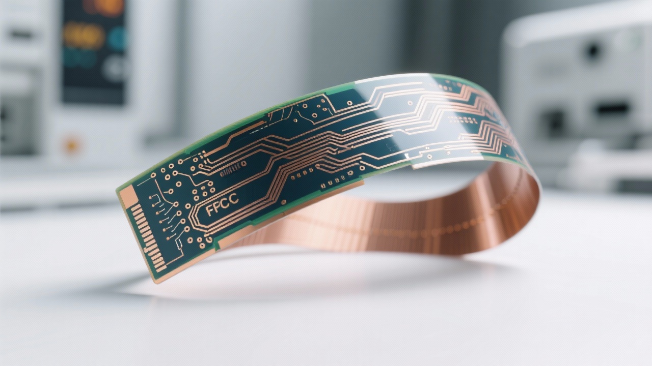
High-performance dielectric materials play a crucial role in maintaining impedance stability. Materials like ISOLA 370HR and MENTRON6 have excellent electrical properties, such as low dielectric constant and low loss tangent. These properties allow them to better control the impedance of the PCB. In contrast, traditional dielectric materials may have higher dielectric constants and loss tangents, which can lead to greater signal loss and impedance variation.
Comparative tests show that using high-performance dielectric materials can reduce signal reflection by up to 30% compared to traditional materials.
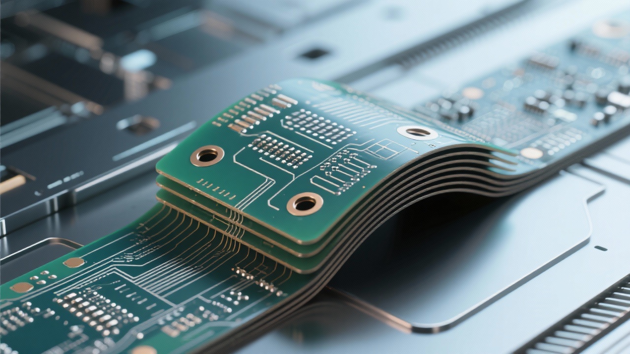
Manufacturing tolerances, including line width, pad spacing, and via filling, can significantly affect impedance consistency. For example, a deviation in line width can change the characteristic impedance of the signal line. A 3-mil line width/spacing and a 20-mil BGA pad spacing are common specifications in high-precision PCB manufacturing to ensure impedance consistency. Additionally, proper via filling can also reduce the impact of vias on impedance.
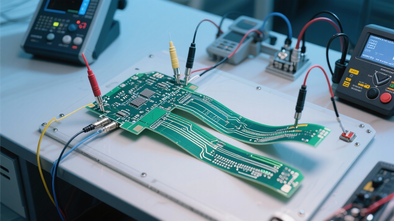
AOI (Automated Optical Inspection) testing and simulation verification are essential tools for ensuring impedance control. AOI testing can detect any physical defects on the PCB, such as short circuits or open circuits, which can affect impedance. Simulation verification, on the other hand, can predict the impedance characteristics of the PCB during the design phase, allowing engineers to make adjustments to the design to ensure impedance stability.
Studies have shown that using AOI testing and simulation verification can increase the impedance control accuracy by up to 25%.
You may wonder, have you ever encountered signal anomalies caused by unstable impedance? If you are a high-speed multilayer PCB engineer, this article provides a practical path for impedance control. By using high-performance dielectric materials, controlling manufacturing tolerances, and applying AOI testing and simulation verification, you can effectively improve the impedance stability of your PCB designs.
Are you ready to take your high-speed PCB designs to the next level? 立即获取我们的《高频PCB阻抗控制白皮书》或预约技术咨询,提升你的设计成功率。
 402
|
402
|
 FPC high-density routing
flexible circuit board design tips
EMC optimization
high-density PCB trace spacing
flexible printed circuit manufacturing
256
|
multilayer flexible pcb via design
high-density fpc routing
fpc electromagnetic compatibility
flexible circuit board manufacturing capability
fpc bend zone reliability
298
|
FPC high - density wiring
Flexible circuit board design skills
Electromagnetic compatibility optimization
Signal crosstalk protection
High - reliability FPC manufacturing
259
|
Impedance control
High-frequency PCB
5G base station PCB
Signal integrity
High-speed multilayer PCB
377
|
FPC high-density routing
flexible PCB design
trace spacing control
high-density PCB manufacturing
electromagnetic compatibility
FPC high-density routing
flexible circuit board design tips
EMC optimization
high-density PCB trace spacing
flexible printed circuit manufacturing
256
|
multilayer flexible pcb via design
high-density fpc routing
fpc electromagnetic compatibility
flexible circuit board manufacturing capability
fpc bend zone reliability
298
|
FPC high - density wiring
Flexible circuit board design skills
Electromagnetic compatibility optimization
Signal crosstalk protection
High - reliability FPC manufacturing
259
|
Impedance control
High-frequency PCB
5G base station PCB
Signal integrity
High-speed multilayer PCB
377
|
FPC high-density routing
flexible PCB design
trace spacing control
high-density PCB manufacturing
electromagnetic compatibility


-4.png?x-oss-process=image/resize,m_fill,h_800,w_800/format,webp)


-1.png?x-oss-process=image/resize,h_800,m_lfit/format,webp)


