
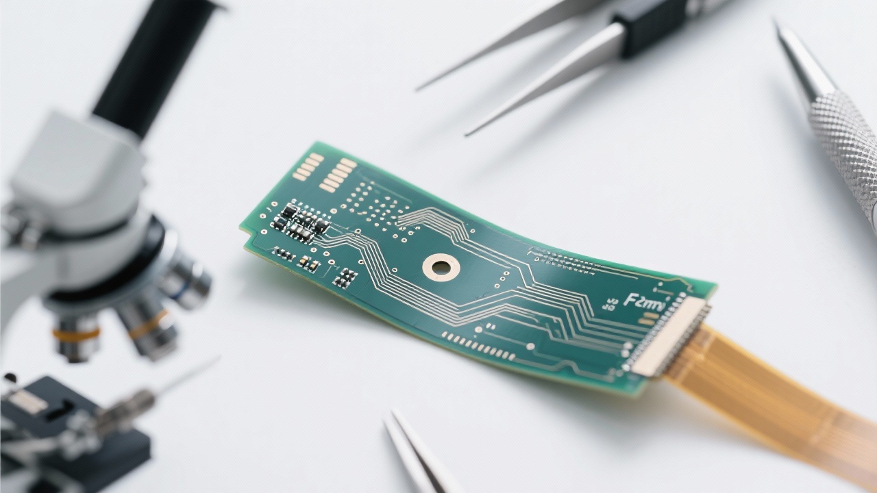
In the design of high-speed multilayer PCBs, impedance control stands as the core element for ensuring signal integrity. This article delves deep into the standard principles of 50-ohm single-ended and 100-ohm differential impedance, as well as their impact on high-frequency signal transmission.
Understanding the basic physical mechanisms of impedance control is crucial for engineers. Impedance is essentially the opposition that a circuit presents to a current when a voltage is applied. In high-speed PCB design, the difference between single-ended and differential impedance applications needs to be clearly distinguished. Single-ended impedance is mainly used for single-signal transmission, while differential impedance is used for differential signal pairs, which can effectively reduce electromagnetic interference.
The 50Ω and 100Ω standards have significant engineering implications. A 50Ω single-ended impedance is a common standard in high-frequency circuits. It can minimize the reflection of signals and ensure efficient signal transfer. For differential signals, a 100Ω differential impedance can maintain the balance of the two signals in the differential pair, reducing crosstalk and improving signal quality. For example, in a 5G base station PCB, adhering to these standards can significantly enhance the performance of the communication system.
High-performance dielectric materials, such as ISOLA 370HR and MENTRON6, play a vital role in impedance stability. These materials have low dielectric loss and stable dielectric constants, which are essential for maintaining consistent impedance throughout the PCB. The uniform dielectric properties of these materials can reduce the impact of environmental factors on impedance, ensuring reliable high-frequency signal transmission. For instance, in a high-speed PCB with a length of 10 cm, using these high-performance materials can reduce impedance variations by up to 5%.
Manufacturing tolerance management, including line width, pad spacing, and via filling, has a significant impact on impedance consistency. Precise control of these parameters is essential for achieving stable impedance. For example, a tolerance of ± 3mil in line width and spacing can ensure that the impedance deviation is within an acceptable range. Inadequate tolerance control can lead to impedance mismatches, resulting in signal reflection and crosstalk, which can severely degrade the performance of the PCB.
In mass production, impedance measurement methods, such as simulation and AOI testing, are essential for ensuring impedance accuracy. Simulation can predict impedance characteristics during the design phase, allowing engineers to make necessary adjustments. AOI testing can detect any impedance irregularities in the manufactured PCBs. By combining these two methods, engineers can effectively control impedance and improve the reliability of the products. In a production line with a monthly output of 10,000 PCBs, using these measurement methods can reduce the defect rate related to impedance issues by up to 10%.
In a 5G communication module project, the engineering team faced challenges in achieving stable impedance. By using ISOLA 370HR material, optimizing the stack-up structure, and strictly controlling manufacturing tolerances, they successfully reduced signal reflection and crosstalk. The use of simulation and AOI testing ensured the accuracy of impedance, improving the overall performance of the communication module.
Mastering the key points of high-frequency PCB design, especially impedance control, is crucial for engineers in the telecommunications and communication equipment design fields. If you are looking to enhance the reliability of your products, learn more about high-reliability PCB solutions that support 5G and high-frequency applications.
 360
|
360
|
 FPC Hochdichte Leiterbahnen
Flexible Leiterplatten Design
Elektromagnetische Verträglichkeit FPC
Hochpräzise FPC Fertigung
FPC Zuverlässigkeit
291
|
Hochgeschwindigkeits-Multilayer-PCB
Impedanzkontrolle
5G-Kommunikationsmodul
Hochfrequenz-PCB-Design
AOI-Test
412
|
Doppelschicht-PCB
Schnellfertigung von PCB
Oberflächenbehandlungstechnologie
Flying-Probe-Test
PCB-Produktionsprozess
96
|
FPC Hochdichte - Verdrahtung
Flexibles Leiterplatten - Entwurfstechniken
Optimierung der elektromagnetischen Verträglichkeit
Hochdichte - flexible Leiterplatten
Fertigungsprozesse für mehrlagige FPC
325
|
FPC hochdichte Verkabelung
flexible Leiterplatten-Design-Tricks
Via-Design-Herausforderungen
EMC-Optimierung
flexible PCB-Fertigungsprozess
FPC Hochdichte Leiterbahnen
Flexible Leiterplatten Design
Elektromagnetische Verträglichkeit FPC
Hochpräzise FPC Fertigung
FPC Zuverlässigkeit
291
|
Hochgeschwindigkeits-Multilayer-PCB
Impedanzkontrolle
5G-Kommunikationsmodul
Hochfrequenz-PCB-Design
AOI-Test
412
|
Doppelschicht-PCB
Schnellfertigung von PCB
Oberflächenbehandlungstechnologie
Flying-Probe-Test
PCB-Produktionsprozess
96
|
FPC Hochdichte - Verdrahtung
Flexibles Leiterplatten - Entwurfstechniken
Optimierung der elektromagnetischen Verträglichkeit
Hochdichte - flexible Leiterplatten
Fertigungsprozesse für mehrlagige FPC
325
|
FPC hochdichte Verkabelung
flexible Leiterplatten-Design-Tricks
Via-Design-Herausforderungen
EMC-Optimierung
flexible PCB-Fertigungsprozess
-4.png?x-oss-process=image/resize,h_800,m_lfit/format,webp)


-L4-4.png?x-oss-process=image/resize,m_fill,h_800,w_800/format,webp)


-4.png?x-oss-process=image/resize,m_fill,h_800,w_800/format,webp)